
BUILDING THERMAL MASS · TECHNICAL ARTICLE
How Much Heat Can a Building Actually Store in Six Hours?
Comparison of Air Heating, Direct Thermal Radiation and Building Component Activation
← Articles1. Research question
Buildings contain substantial thermal mass. Walls, ceilings, floors and furnishings can absorb heat, store it temporarily and release it with a time delay.
It is therefore reasonable to consider using this existing storage potential to accommodate surplus photovoltaic energy. For example, a heat pump can supply additional heat during sunny hours in order to reduce heating demand in the evening and at night.
However, the total calculated heat capacity of a building’s mass must not be equated with its short-term usable thermal storage capacity. What matters is how much heat can actually be transferred into the structures within a limited period.
Three basic heat-input pathways are compared: (1) heating via room air, (2) direct heating of surfaces by thermal radiation, and (3) direct introduction of heat into a structural layer, such as the screed of an underfloor heating system. Only additional thermal storage relative to an unchanged initial state is considered.
2. Common basis of calculation
The reference is a room with a floor area of 20 m², dimensions of 4 × 5 m and a room height of 2.5 m. Initial temperature of both room air and building components: 21 °C. Analysis period: six hours. Comparison limit: no more than +0.5 K additional room-air temperature. Heat losses to the outside are excluded from this initial investigation.
| Element | Assumed value |
|---|---|
| Brick walls | 45 m² surface area |
| Screed layer (model floor) | 20 m² surface area; 6 cm modelled layer |
| Concrete ceiling | 20 m² surface area |
| Total room-enclosing surfaces | 85 m² |
| Furnishings | 150 kg thermally effective mass; 15 m² effective surface area |
2.1. Thermally active mass
A 12 cm model layer is considered for the brick walls. For a 24 cm internal wall exposed symmetrically, this corresponds to modelling half of the wall up to the adiabatic plane of symmetry. The ceiling is represented by a 10 cm layer, and the model floor solely by a 6 cm screed layer. The rear boundaries of the modelled layers are adiabatic; no additional concrete substructure beneath the screed is included in this calculation.
The temperature distribution within the building components is calculated as a function of time. The modelled mass is therefore not assumed to warm uniformly by the same amount. The depth limit defines the reference case; it does not imply that real buildings can thermally utilize only layers of these thicknesses.
2.2. Heat transfer and calculation approach
The model includes convective heat transfer between room air and surfaces, long-wave radiative exchange between surfaces, transient heat conduction into the building components, and the heat capacities of the materials and furnishings.
| Component / mechanism | Model value |
|---|---|
| Convection at walls | 2.5 W/(m²·K) |
| Convection at floor | 1.5 W/(m²·K) |
| Convection at ceiling | 3.0 W/(m²·K) |
| Convection at furnishings | 2.5 W/(m²·K) |
| Linearized radiative exchange | 5.0 W/(m²·K) |
The following results come from a linear dynamic thermal-network model. The convection and radiation coefficients are held constant within each calculation case. The results are reproducible reference values for the defined model room; they are neither measured data nor general performance figures for buildings or heating systems.
2.3. Material parameters, discretization and numerical method
The archived original model uses 58 temperature nodes: 24 nodes for the brick wall, 12 for the screed, 20 for the ceiling, and one lumped node each for the furnishings and room air. The solid layers are discretized into 5 mm cells. Time integration uses scipy.integrate.solve_ivp with the BDF method, adaptive internal time steps, rtol = 10⁻⁹ and atol = 10⁻¹².
| Component | λ [W/(m·K)] | ρ [kg/m³] | cp [J/(kg·K)] | Thickness | Discretization |
|---|---|---|---|---|---|
| Brick wall | 0.70 | 1,800 | 840 | 0.12 m | 24 × 5 mm |
| Screed | 1.40 | 2,000 | 900 | 0.06 m | 12 × 5 mm |
| Concrete ceiling | 1.70 | 2,300 | 880 | 0.10 m | 20 × 5 mm |
| Furnishings | — | — | 1,600 | 150 kg | 1 node |
| Room air | — | 1.2 | 1,005 | 50 m³ | 1 node |
For each material node, Cᵢ = A · Δx · ρ · cp. Adjacent cells are coupled through g = λ · A / Δx. Between the first material cell and room air, g = hconv · A applies. Long-wave exchange between the four aggregated surfaces is represented in an energy-conserving manner, but without geometrically calculated view factors, using gᵢⱼ = 5.0 · Aᵢ · Aⱼ / Atot. This radiation distribution is expressly a modelling simplification.
The original model was rerun without changes. The unrounded total results after six hours are 551.87398855 Wh (air), 1,503.09850861 Wh (radiation) and 1,820.14955650 Wh (screed). The rounded figures used in this article are therefore fully reproducible.
3. Model 1 – Heating via room air
In the model, the room air is set immediately at t = 0 to +0.5 K relative to its initial state and then held at precisely that level for six hours. The time-dependent heating-power profile needed to achieve this is not calculated; the analysis concerns only how much additional energy passes from this prescribed air temperature into surfaces and building components.
Initially, the internal surfaces remain at the initial temperature. Additional heat enters the components through their surfaces. As the components warm, the temperature difference relative to room air decreases, and with it the additional heat transfer.
3.1. Result after six hours
| Element | Additional heat |
|---|---|
| Brick walls | 274 Wh |
| Concrete floor / screed | 92 Wh |
| Concrete ceiling | 159 Wh |
| Furnishings | 19 Wh |
| Room air | 8 Wh |
| Total | 552 Wh |
At the end of the period, the modelled additional surface temperature of the brick wall is approximately +0.17 K, well below the +0.5 K increase in air temperature. This limits the short-term thermal activation of the component mass farther inside.
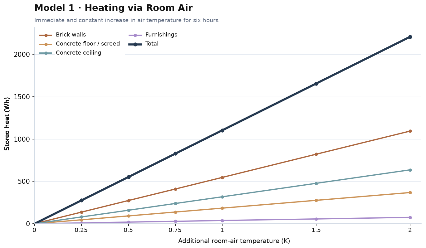
Figure 1. Additional heat stored during a constant increase in room-air temperature over six hours. The small difference between the four material curves and the total curve corresponds to the heat stored in room air.
4. Model 2 – Direct heating of surfaces by thermal radiation
Here, the additional heating power is idealized as being distributed entirely to internal surfaces by radiation. No convective fraction from the heat source is considered. The power fractions of 45/25/20/10% are prescribed model fractions rather than view factors calculated from the room geometry. Heated surfaces then release heat to the room air and other surfaces while simultaneously conducting heat deeper into the building components.
| Directly irradiated surface | Share of radiant power |
|---|---|
| Brick walls | 45% |
| Floor | 25% |
| Ceiling | 20% |
| Furnishings | 10% |
The additional radiant power remains constant throughout the six hours. Unlike in the first model, room-air temperature is not prescribed over the entire period; it is the outcome of heat transfer. The radiant power is sized so that an additional room-air temperature of +0.5 K is reached at the end.
4.1. Result after six hours
| Element | Additional heat |
|---|---|
| Brick walls | 719 Wh |
| Concrete floor / screed | 348 Wh |
| Concrete ceiling | 381 Wh |
| Furnishings | 46 Wh |
| Room air | 8 Wh |
| Total | 1,503 Wh |
The additional thermal power required for this case is approximately 251 W in the model. Radiant energy reaches the component surfaces directly during charging, while the room air warms only subsequently. As a result, the heat stored over six hours exceeds that in the defined air-only case.
The result depends substantially on the radiation distribution, source position, degree of obstruction and properties of the surfaces struck by the radiation. A real electrically operated infrared heater generally also has a convective component; this simplified calculation deliberately represents a limiting case of pure radiation.
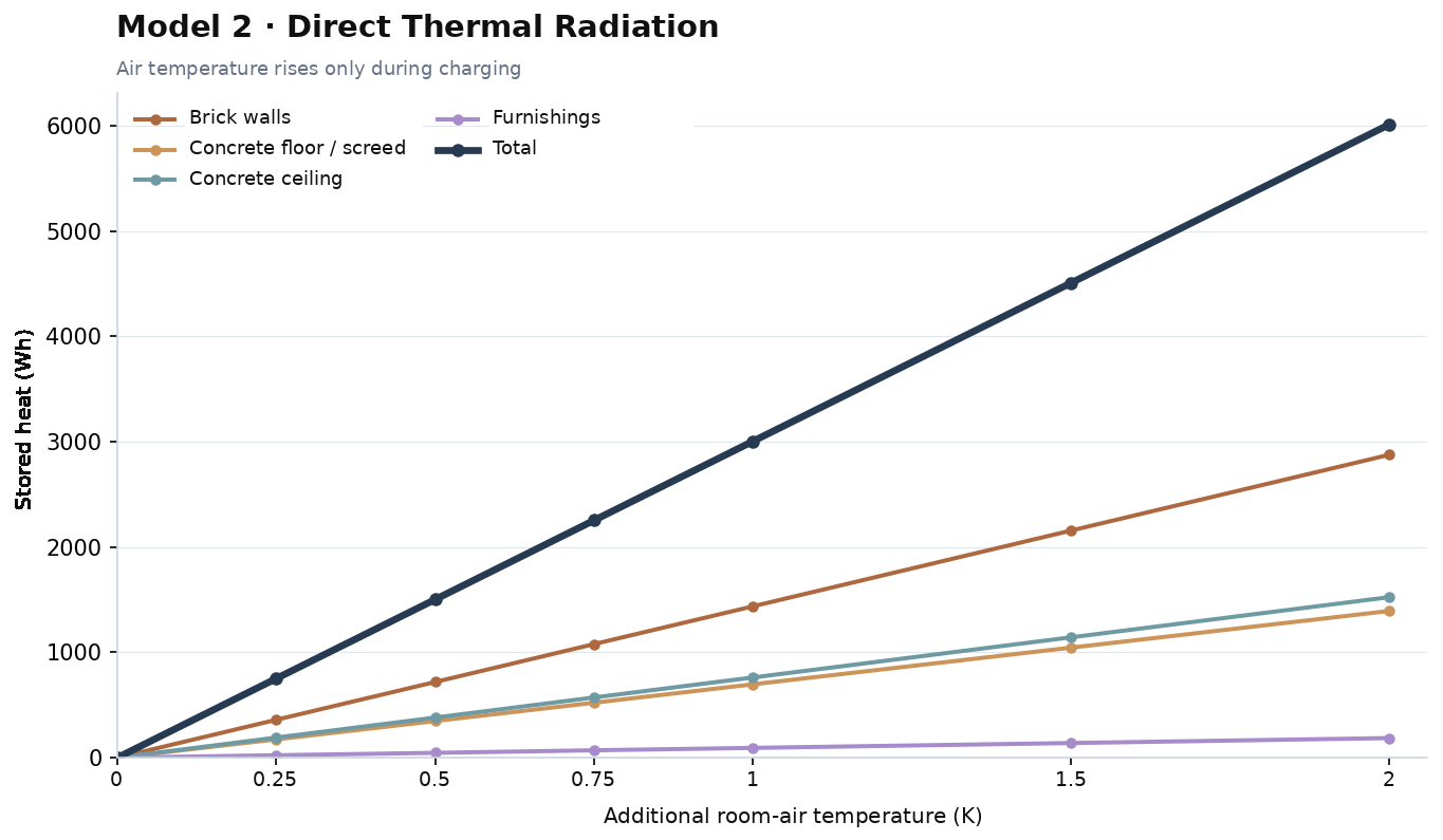
Figure 2. Storage under idealized direct irradiation of internal surfaces; the room air reaches the additional temperature indicated on the horizontal axis only after six hours.
5. Model 3 – Direct introduction of heat within the structure
In the third model, additional energy is introduced directly into the thermal storage mass. The example considers only the 6 cm screed layer of the model floor; the heat source is distributed uniformly between two 5 mm nodes at a depth of approximately 3 cm. The underside of the screed layer is adiabatic. A concrete substructure, pipe system or hydronic heat input is not part of this reference model.
The screed around the heat source warms first. Heat spreads within the structure and reaches the floor surface over time. That surface then releases heat by convection and radiation, causing the room air, walls, ceiling and furnishings to absorb increasing amounts of heat as well.
Direct, primary storage within the screed is superimposed on subsequent, secondary storage in the other elements. The additional thermal power remains constant and is selected so that an additional room-air temperature of +0.5 K is reached after six hours.
5.1. Result after six hours
| Element | Additional heat |
|---|---|
| Brick walls | 360 Wh |
| Floor / screed | 1,221 Wh |
| Concrete ceiling | 195 Wh |
| Furnishings | 35 Wh |
| Room air | 8 Wh |
| Total | 1,820 Wh |
The additional thermal heating power in this model is approximately 303 W. The screed accounts for the largest share of additional heat storage. At the end, its surface is approximately 1.9 K above the initial temperature, whereas the room air is only 0.5 K warmer.
The model assumes an ideally and uniformly heated screed. Pipe spacing, pipe material, heat transfer from water, volume flow, supply and return temperatures, and the actual layer sequence are not represented for any particular installation. The result therefore does not constitute a generally attainable storage capacity for arbitrary underfloor heating systems.
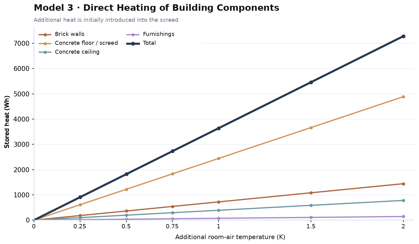
Figure 3. Direct thermal activation of the screed and delayed warming of the other room surfaces.
6. Comparison of the three heat-storage pathways
| Type of heat input | Additional heat after 6 h | Energy / 6 h as mean comparison power |
|---|---|---|
| Via room air | 0.55 kWh | approx. 92 W |
| Directly by radiation | 1.50 kWh | approx. 251 W |
| Directly into the screed | 1.82 kWh | approx. 303 W |
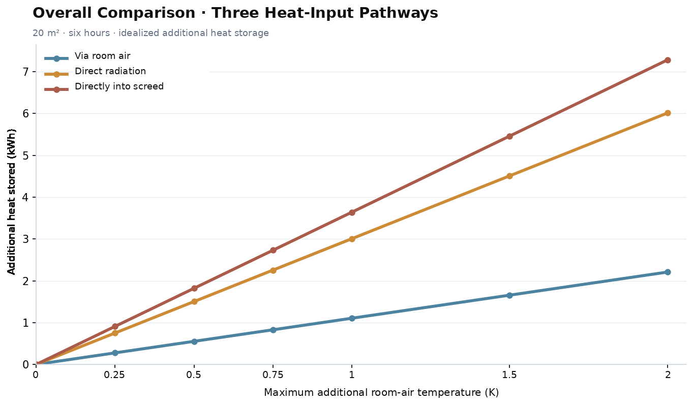
Figure 4. Comparison of total additional heat storage in the three defined cases. Values shown outside the calculated +0.5 K reference point were scaled linearly in proportion in the chart script and were not separately simulated. This scaling is to be interpreted only within the assumptions of the linear model.
All three approaches share the same final limit of +0.5 K room-air temperature, but expressly not the same time profile: in the air case, the additional temperature is present throughout all six hours; in the other cases, it is not reached until the end. This compares defined limiting cases and does not assess identical comfort conditions over time.
The additional thermal powers must not be equated with the electrical rated power or electricity draw of a heat pump. Likewise, the storage figures must not be read directly as differences in the annual efficiency of heating devices.
7. Technical interpretation
The short, six-hour charging period limits how much mass can actually be thermally activated. The heat-input pathway determines which surfaces and layers absorb heat first and how much energy can be stored before a specified room-air temperature is reached.
When heating via air, small temperature differences and surface heat-transfer coefficients limit heat flow into the building structures.
With direct irradiation, heat is introduced at the surfaces. Its distribution depends on the radiation pattern.
With direct heating of a structural layer, the storage mass is activated locally first, and the room responds with a delay.
The results do not support a general claim that one heating system is more efficient than another. In particular, the additional thermal powers must not be equated with electrical input power or the COP of a heat pump. In real heat pumps, changes in supply and return temperatures can affect COP; moreover, thermal comfort is not described by air temperature alone.
7.1. Sensitivity analysis
To put the absolute figures into context, two simple parameter groups were varied without changing the model structure. The results indicate which parameters particularly influence the three comparison cases.
| Variation | Air [kWh] | Radiation [kWh] | Screed [kWh] |
|---|---|---|---|
| Convective coefficients −30% | 0.419 | 1.499 | 1.836 |
| Reference | 0.552 | 1.503 | 1.820 |
| Convective coefficients +30% | 0.667 | 1.508 | 1.809 |
| Volumetric heat capacities −20% | 0.531 | 1.269 | 1.465 |
| Volumetric heat capacities +20% | 0.567 | 1.716 | 2.181 |
The air case responds particularly strongly to the assumed convective heat-transfer coefficients. The two cases with direct surface or component activation respond more strongly to the assumed heat capacity of the storage masses. The qualitative finding of the reference comparison remains under these variations, but the absolute kWh figures depend on the model assumptions.
8. Model limitations and scope of validity
The comparison applies to the defined 20 m² reference room without heat losses to the outside, ventilation, solar gains or further internal loads.
Long-wave radiative exchange is energy-conserving but uses no geometrically determined view factors. The 45/25/20/10% distribution of radiant-source power is also prescribed.
The three cases have the same final air temperature but not the same comfort conditions over time: in the air case, +0.5 K is present from the outset; in the other cases, +0.5 K is reached only after six hours.
The model floor consists solely of 6 cm of screed with an adiabatic underside. Real underfloor heating systems include further layers as well as hydraulic and control-related limits.
The figures of 0.55 / 1.50 / 1.82 kWh are therefore reference values for this model, not universal thermal storage capacities of buildings.
9. Conclusion
For the defined reference model of a 20 m² room, a six-hour analysis period and a common final limit of +0.5 K room-air temperature, additional storage amounts to approximately 0.55 kWh for heat introduced via room air, 1.50 kWh for idealized direct surface irradiation, and 1.82 kWh for direct activation of the screed layer.
Above all, the comparison demonstrates a dynamic relationship: total existing mass alone does not describe the storage capacity usable over a short period. The relevant factors are heat transfer, time-dependent penetration depth and the location of heat input. The sensitivity analysis also confirms that the absolute figures depend on the assumed heat-transfer coefficients and material heat capacities. The results should therefore be used to compare defined heat-input pathways, not as a general building performance metric.
Calculation documentation
The complete original calculation state—including the Python model, material parameters, 58-node time series, JSON/CSV raw data, NPZ results file and chart data—is documented in the project archive associated with the publication version. The three rounded reference values were reproduced by rerunning the original model without modification.